boundaryLayout: Visualizing Force-Directed Networks within Custom Boundaries
UCSF boundaryLayout is a
Cytoscape
app that links
which implements a boundary-constrained force-directed layout. Boundaries
may be automatically generated or defined by the user, who can later save
and modify them as a “template”, or a collection of boundaries. This
app groups data into custom boundaries to effectively create an
n-partite network. The force-directed algorithm is derived from the
prefuse algorithm, which is used in other applications such as
setsApp.
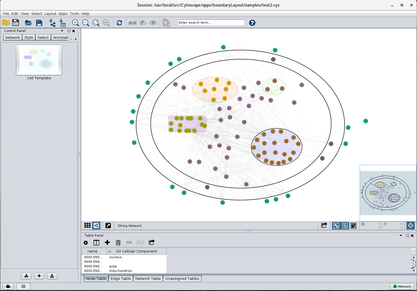
Figure 1.
boundaryLayout in action. In this screenshot,
boundaryLayout has been applied to a network that has been annotated with cellular locations. The cell
image boundaries are used to constrain nodes to the compartment that they have been annotated to be expressed
in. The template used is the default "Cell Template".
Click on the image to enlarge it.
Contents
- Installation
- Starting boundaryLayout
- Boundaries and their uses
- boundaryLayout app
- boundaryLayout layout algorithm
- Boundary-node interaction
- Technical details
boundaryLayout can be downloaded and installed through the
Cytoscape App Store. In order to correctly utilize
boundaryLayout,
you must be running Cytoscape 3.6.0 or newer. One way to install this
application is to launch Cytoscape, go to the
App Store in your web
browser, and search for “boundaryLayout”. Select the "boundaryLayout"
button and press the
Install button in the
boundaryLayout
App page. A simpler way to install it is by launching Cytoscape and
selecting , then search and install "boundaryLayout".
Once you have installed
boundaryLayout, two menus should appear: one
in the Apps menu labeled “Boundary Layout App” and another in the
layout menu titled “Boundary Layout”. The app allows the saving,
deleting, overwriting, importing and exporting of templates, each of
which consist of a collection of boundaries. You can manage templates
in the west control panel under the “Boundaries” tab. While, the
layout is where you are able to layout your nodes based on an attribute.
Boundaries take the form of Annotations (some forms are not supported
such as Arrow Annotations). Boundaries are mainly used for grouping and
partitioning data based on selected attributes like Cellular Location
or Species. Boundaries should be created by the user according to which
attribute they would like the algorithm to run on. For example, if the
column attribute the user wanted to use was “Letters” and the nodes
in the network table contain “Letters” properties ‘A’, ‘B’,
and ‘C’ within the “Letters column”, then the user should create
three Annotations and name them ‘A’, ‘B’, and ‘C’.
3.1 Cytoscape Annotations that can be used as boundaries
Annotations that can be used as
boundaries are Rectangle, Round Rectable, and Ellipse annotations which belong to
shape annotations, along with its subclasses: bounded-text annotations
and image annotations (~Rectangle only).
3.2 How to use boundaryLayout
Although the boundary layout algorithm
can be run without utilizing its boundary-based features, in order to
get the full use of this application, boundaries should be created by
the user. Boundaries should be created according to what attribute the
user wants to layout the nodes with respect to. When the user wants
to perform the layout on an attribute, there should exist boundaries
with names of each of the variations of that attribute that exist in
the network table. Otherwise, if one of the variations is not created,
then the nodes of that variation, which does not contain a boundary,
will be placed outside of the union of boundaries.
This app appears by default in the western control panel, titled
Boundaries. To toggle between hiding and showing the panel in the
, simply select
or
.
The main purpose of this app is for the user to be able to
manage and customize their templates, each being a related collection
of boundaries. A template consists of user-defined boundaries that the
user classifies as belonging together. An example of a template is the
, which is provided by default by
boundaryLayout, in which
there exist boundaries such as “Nucleus” and “Cytoplasm”.
4.1 Importing/Exporting a Template
At the bottom of the Boundaries panel, there are three buttons. The two
outer ones are the import/export buttons. You can hover over the buttons
to see what each do. To import a template click on the
import a template (leftmost) button and input your template name
choice and the location of where the template information is stored.
To export a template, choose the template from your templates list and
select the
export a template (rightmost) button and select
the
location to export the template to.
4.2 Saving/Overwriting a Template
To save a template, press the
+ button at the bottom of the
Boundaries panel. If you are currently working on a template, you will
be prompted to overwrite the current template. To overwrite the template,
check the checkbox and press
OK. To save as a new template, do not check
the checkbox and press
OK. If you select a template name which is the
same as that of a template that already exists in your list of templates,
then that template will be overwritten.
4.3 Removing/Deleting a Template
To remove a template from your list of templates, right click on the
desired template which appears in the Boundaries tab and select
.
You will then be prompted to validate your removal of
the template.
4.4 Renaming a Template
To rename a template, right click on the desired template in your list of
templates and press . You will then be prompted to
enter a new name for the template. However, if the name already belongs
to another template, nothing will happen.
4.5 Applying a Template to the View
To apply a template to your view, simply press the template you would like
to apply in the Boundaries panel. To switch templates, press whatever
other template you would like to apply. Only a single template can be
applied at any given point in time.
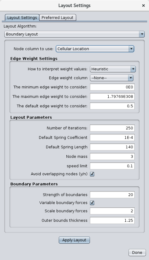
Figure 2.
boundaryLayout settings.
The layout submenu “Boundary Layout” is populated based on the columns
of the current network that is shown. To layout your data, simply select
category where
category is one of the columns,
or properties, in the node table.
5.1 Auto Mode
If there do not exist any boundaries, then auto mode is run. This mode
creates boundaries for each of the attributes of the selected category
and places them in a grid. After the boundaries are initialized, the
algorithm is executed normally.
5.2 Tuning Parameters
Running Boundary Layout from the is well-advised
since it provides the user access to tune parameters which affect the
layout of a network.
5.2.1 Edge Weight Settings
These values are generalized by Cytoscape and are not specific to
boundaryLayout. They enable the user to tune edge weights and how to
interpret edge-related properties of the network.
5.2.2 Layout Parameters
Ranging from spring and node related information to the speed limit,
layout parameters allow the user to tune the parameters which are relevant
to prefuse. The
controls how many iterations
the force-directed algorithm will run.
For a more force-representative
network, increase this value. However, for best results, keep this value around 250 and no
more than 1000. For the connections between nodes, or edges, to impact
the network more, increase the
, but maintain a value
ranging from 5x10⁻² to 5x10⁻⁶. The
is the resting
edge length.
controls the weight of a node. When increased,
this pushes nodes away from one another while slowing down the overall
movement of the node. Keep this value around 3, in the range of 1-10. The
is the limit of how fast a node can move; this value should
stay near 1. When enabled,
pushes overlapping
nodes farther away from one another so that there is overall less
node-node overlap.
5.2.3 Boundary Parameters
controls the repulsive force of boundary
walls. The larger this value, the more nodes are pushed to the center
of their respective boundary and pushed away from its walls.
checkbox should be checked if the user wants the boundary
walls to be scaled as more nodes are at the edge of the boundary. The
magnitude of the boundary strength scaling is determined by
.
For less nodes stuck at the edge of boundaries, check the checkbox
and increase the value of this scaling parameter.
is the thickness of the outer boundary, which encompass the union of
boundaries. For extra-spatial nodes, or nodes which do not belong to a
boundary, to be closer to the union of boundaries, decrease this value,
though keep it is advised to keep this value around 1.25.
5.3 The Outer Boundary
boundaryLayout creates an outer boundary which encompasses the union of
user-defined boundaries. This outer boundary serves multiple purposes. The
outer boundary behaves just like any other boundary, but it does not
have a shape annotation associated with it.
5.3.1 Boundary Dimensions
By default the dimensions of the outer boundary is 1.25 times as large
as the union of boundaries. However, the user can change this outer
dimensions scale within the layout settings menu, which must satisfy
the precondition that the scale is greater than 1.
5.3.2 Affirming Outer Boundary Nodes
Nodes which do not belong to any of the boundaries the user has defined
can be referred to as “outer” nodes and are by default assigned
to the outer boundary. This tells the algorithm where to initialize
these nodes: outside the other user-defined boundaries, but within the
outside boundary.
5.3.3 Keeping the Boundaries Property
The outer boundary makes it so that outer nodes do not move far away
from the union of boundaries. Instead, they are treated as an “other”
attribute, corresponding to the outer boundary.
5.4 The Prefuse Algorithm
The prefuse algorithm utilizes force-directed logic to position
nodes at their relatively ideal locations. It accomplishes this by,
with each iteration, calculating the force on each node and moving the
nodes based on the integrated force applied on them using a Runge-Kutta
Integrator. Each node was represented by a ForceItem, containing various
of its properties such as velocity, location, and dimensions. Two main
types of node-node based forces exist: Spring and NBody.
5.4.1 Spring Force
Since nodes with edges between them should be closer together to
establish a relationship-based network, the spring was integrated into
prefuse. Spring forces are placed between two nodes if there exists an
edge connecting them, leading to the attraction of the two nodes if they
are farther apart than ideal length or repulsion if they are too close.
5.4.2 NBody Force
There is always the issue of nodes clumping together and forming a
“hairball” network due to the numerous active attractive and repulsive
forces resulting from the spring and boundary forces. To solve this issue,
the NBody force was introduced, which allows prefuse to be substantially
more effective and efficient. This force exists only among nodes that
are close together, calculated by a QuadTree, and makes it so that nodes
do not clump together, allowing the network to be readable by the user.
5.5 Avoiding Overlap
When the user looks at a Cytoscape network after running some algorithm,
the worst outcome is a counterintuitive “hairball” of nodes where
most of what the user is able to see is a clump of nodes. The method
in which
boundaryLayout handles these dense networks is by avoiding
overlap between nodes. Since NBody deals with nodes that are close
together and two nodes may only overlap if they are near one another,
the avoiding overlap logic is implemented in complement with NBody
forces. This approach is efficient since NBody already iterates through
a QuadTree to figure out which nodes are close to one another, so no
further calculations need to be made for the avoiding overlap force. In
essence, when two nodes overlap, then they both experience a force in
the opposite direction of one another.
This force corresponds to a boundary-node interaction. The purpose of
a boundary is to ensure that the nodes which belong to that boundary
stay within and nodes which do not belong to it remain outside of the
boundary. This property is accomplished by the boundary force, which
exerts a repulsive force on nodes. Furthermore, the boundary force make it
so that, when a node becomes too close to the wall of the boundary, then
a force will be applied such that the node will either stay where it is
or move away from the wall it was approaching. As with the other forces,
the forces from the walls of the boundary depreciate with respect to
the square of the distance from the wall. In other words, the wall force
only becomes a factor when nodes are not where they are supposed to be,
otherwise NBody and Spring forces drive the expression of the network.
6.1 Node Projections
Node projection is the mechanism by which the algorithm moves (projects)
the nodes into or out of the boundaries as appropriate. The general approach
followed by
boundaryLayout is an adaptation of an algorithm
suggested by Tim Dwyer of the University of Monash.
There are two cases in which a node projection is required. The first
case occurs when the node is moved outside of its respective boundary as
a result of the force-directed simulation. When this happens, the node
must be projected back into its boundary. The second case is when the
node is moved into another boundary, which only occurs in the case of
intersecting boundaries. In this case, the node is projected outside
of this intersected boundary. These nodes are projected to a point
closest to their respective boundary. For an inward projection, the
node is moved to a point in which it is just within its boundary. For
an outward projection, the node is moved such that it is just outside
the boundary it was in and also within its own boundary.
6.2 Variable Boundary Force
A variable, or changing,
boundary force is a feature of
boundaryLayout, which is by default active
but the user can deactivate it through the layout settings menu. There
are two gravitational constants for the boundary force: one for nodes
which belong to the boundary and another for nodes which do not belong in
the boundary. For a specific boundary, as nodes that have been moved out
of their boundary are projected back into it, the inward gravitational
constant of that boundary is scaled. The same applies for nodes which
move into a boundary, which intersects with the boundary they belong
to. The intersected boundary’s outward gravitational constant is scaled
accordingly. This gravitational constant scale factor is by default 2.5,
but can be changed by the user as long as it fits the precondition that
it is greater than 1 and less than the large factor 10. The purpose of
this variable boundary force is to ensure that nodes do not become stuck
at the edges of boundaries and so that less overall node projections
are needed. This feature both speeds up the layout algorithm as well as
provides a more appealing network layout.
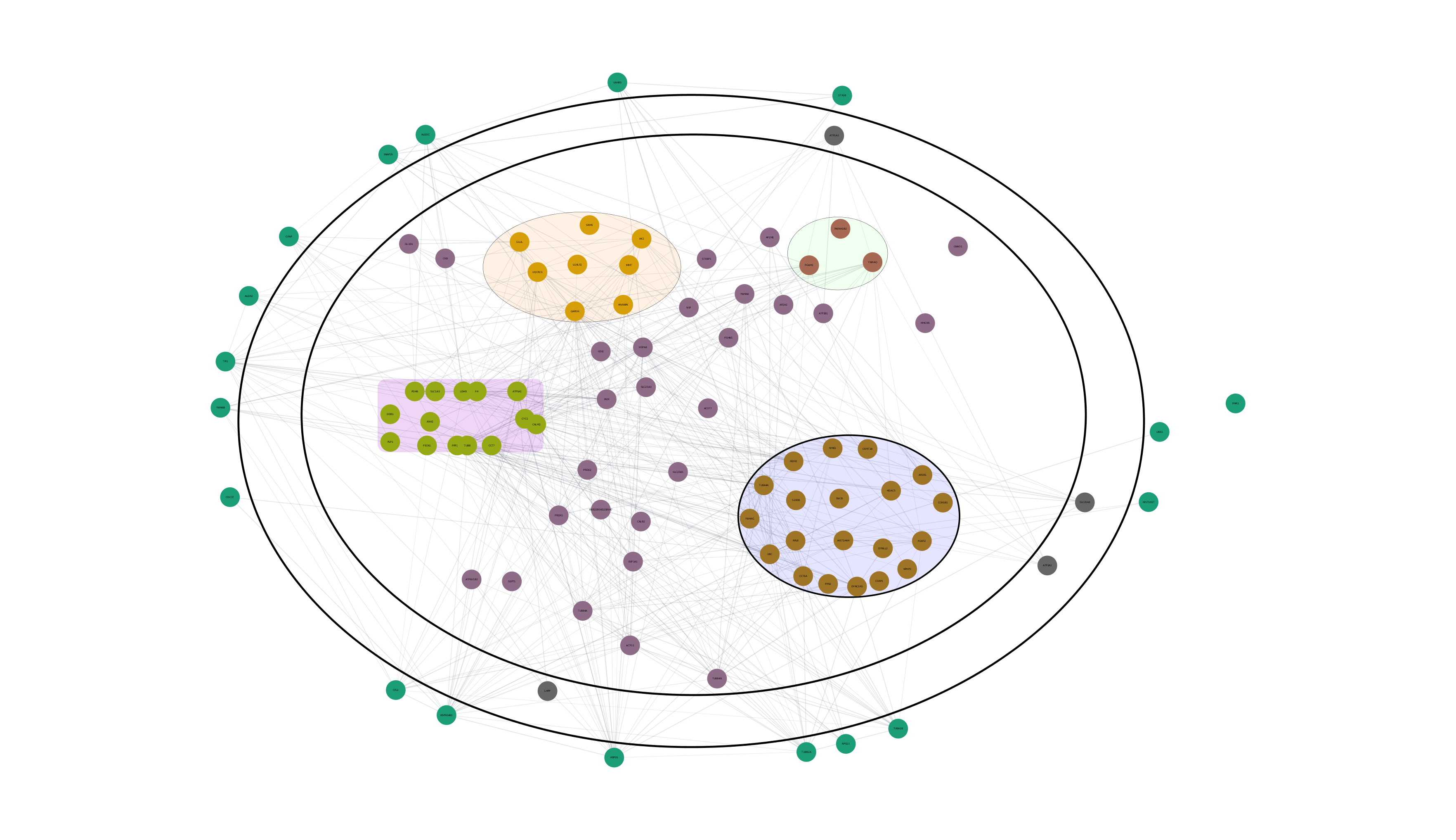
Figure 3.
Result of applying boundaryLayout using the Cell Template.
7.1 Initializing Nodes’ Locations
In order to run the prefuse algorithm on a network, nodes must first be
placed within the boundaries they belong to. There are two scenarios
which can arise with boundaries wherein the initialization of nodes
differs. Node initialization into a specific boundary depends on whether
or not that boundary has any intersecting boundaries.
7.1.1 Calculating the Non-Intersected Areas within an Intersected Boundary
To deal with special cases, including an edge case with node projection,
boundaryLayout can find the non-intersecting area within a boundary
to re-initialize nodes if needed. This is achieved using an efficient
branch and bound algorithm which uses a quadtree to speed up the spatial
complexity of multiple intersecting boundaries. After the algorithm
has finished, the result is a quadtree whose leaves are rectangles
representing the non-intersecting areas in the boundary.
7.1.2 Boundaries Without Intersections
Nodes who belong to a boundary without intersecting boundaries are
initialized at the center of that respective boundary.
7.1.3 Boundaries With Intersections
Since boundaries with intersections complicates node initialization,
the nodes are initialized within the center of the union of intersecting
boundaries. Then, the projection algorithm (5.1) ensures the boundary-node
property.
7.1.4 Initializing Nodes Without Boundaries
When the user has not defined a boundary for a certain node, the node
belongs outside of the union of boundaries. Although it is initialized
in the center of the union, it is projected outward after numerous
iterations of the force-directed layout.